A staple of electronics projects since 1972 when it was first made available by Signetics, the 555 timer integrated circuit (IC) has long shown its usefulness for a vast range of applications.
This little eight-pin chip is widely used to create timing and oscillation functions in electronic circuits. It has long been greatly admired for its simplicity, robustness, and versatility, not to mention its low cost. Indeed, you can get one for potentially less than 50p from your local component shop, or a reputable online source like RS.
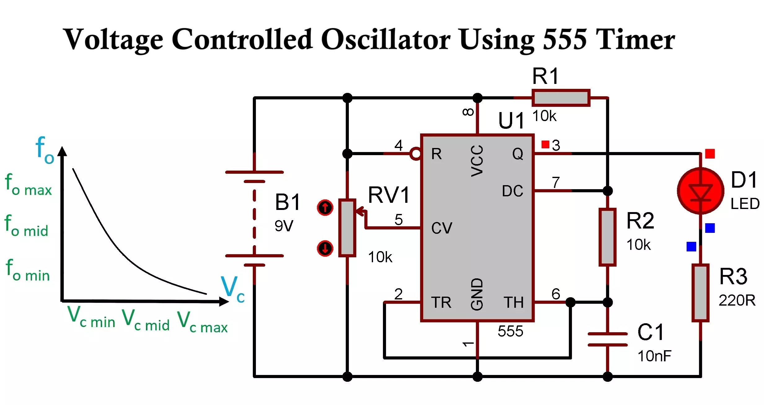
Such qualities make the 555 timer IC ideal for the creation of astable (free-running oscillator) and monostable (one-shot pulse generator) circuits.
Get Your Timings Right to Put The 555 Timer IC to All Manner of Uses
Are you reading this as a student, a professional engineer, or even “just” an electronics hobbyist? If so, you may be keen to master these configurations so that you can get great results from all manner of projects, ranging from basic frequency generators to flashing LEDs.
So, with no further ado, let’s look at how you can set timings for monostable and astable 555 configurations, as well as some other key details to know.
Understanding The Astable and Monostable Modes
There are three fundamental modes that the 555 timer IC operates in: astable, monostable, and bistable. It is the first two of those modes that have particular relevance for timing and oscillation.
- Monostable Mode
This configuration involves the circuit producing a single output pulse of a specific duration when an input signal triggers it.
The behaviour of a 555 timer in monostable mode as a “one-shot” pulse generator lends well to such applications as debouncing switches or the creation of a simple timer for a given duration.
The values of an external resistor (R) and capacitor (C) determine the output pulse’s length.
- Astable Mode
This is a 555 timer’s oscillator configuration. It entails the device continuously producing a square wave output, self-oscillating without any external trigger.
If, then, you are interested in using a 555 timer to create clock signals or LED flashers, or to generate specific tones in a speaker, this mode can rise to the task.
With this configuration, the frequency and duty cycle (the ratio of “on” time to the total period) are controlled by two external resistors (R1, R2) and a single capacitor (C).
External Components Play a Critical Role In 555-Based Oscillator Circuits
The “magic” of the 555 timer IC lies in how it interacts with external passive components. It all revolves around the core principle of a capacitor being charged and discharged through a resistor.
The 555 timer’s internal comparators monitor the voltage of the capacitor, switching the output high or low at certain thresholds (typically one-third and two-thirds of the supply voltage).
Through the careful selection of the resistor and capacitor values in your circuit, you can precisely dictate its timing characteristics.
What Are the Relevant Formulas for Monostable and Astable Modes?
If you’re using monostable mode, you can use the timing formula t = 1.1RC, or alternatively expressed: t = 1.1 x R x C. In this formula, t is the output pulse duration in seconds (s), while R is the value of the timing resistor in ohms (Ω), and C is the value of the timing capacitor in farads (F).
For astable mode, meanwhile, the below formulas can be used:
- Time high formula: Th = 0.693(R1 + R2)C
- Time low formula: Tl = 0.693R2C
- Frequency formula: f = 1.44/((R1 + 2R2)C)
- Duty cycle formula: D = (R1+R2)/(R1+2xR2) x 100
Remember that you don’t have to restrict yourself to manual calculations when using these formulas. You can head to the RS website, for example, and try the 555 timer configuration calculator for astable and monostable circuits.
Indeed, by using such a digital tool, you can greatly help to reduce calculation errors. Making the most of a 555 timer calculator will also save time by allowing for the rapid identification of common and readily available component values that closely match your theoretical needs.
This will certainly help take a lot of time-and-error tedium out of your oscillator circuit project, while assisting your goal of reaching your desired end result as soon as possible.